
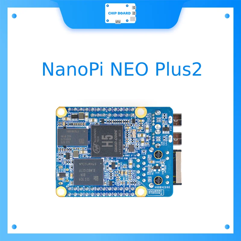
NanoPi NEO Plus2 Allwinner H5 Development Board Performance and Connectivity
The Allwinner H5 processor delivers quad-core ARM performance optimized for edge computing tasks without excessive power consumption, making it ideal for continuous IoT deployments. Gigabit ethernet connectivity transfers data at full wire speed, eliminating network bottlenecks that plague slower boards in production environments. Integrated WiFi and Bluetooth support both wired and wireless operation, giving you flexibility to choose the best connectivity method for your specific application. The industrial-grade construction uses high-quality capacitors and power regulation that withstands temperature fluctuations from 0 to 60 degrees Celsius. This combination of reliable hardware and dual wireless protocols positions the NanoPi NEO Plus2 as a practical choice for remote sensors, edge servers, and distributed computing nodes.
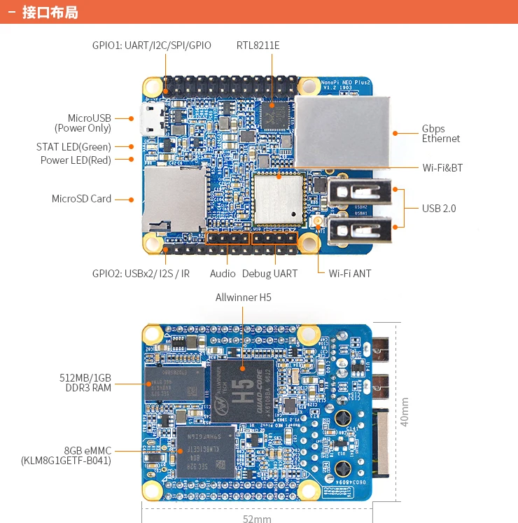
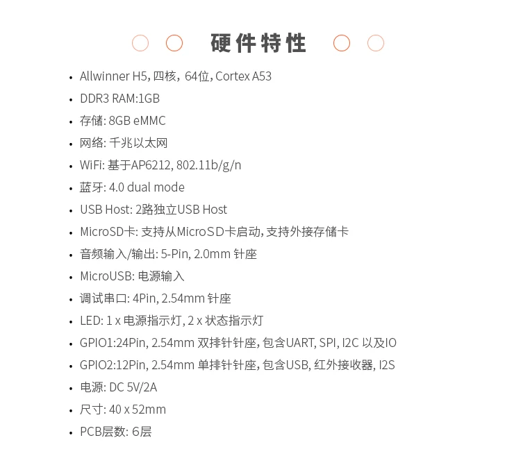
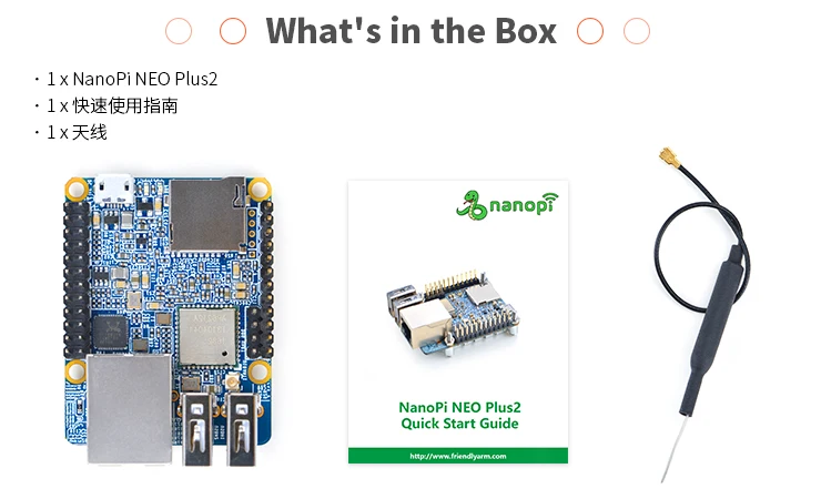
- SoC: Allwinner H5,Quad-core 64-bit high-performance Cortex A53
- DDR3 RAM:1GB
- Storage: 8GB eMMC
- Network: 10/100/1000M Ethernet based on RTL8211E-VB-CG
- WiFi: 802.11b/g/n
- Bluetooth: 4.0 dual mode
- MicroSD Slot: 1 x Slot. It supports system booting or is used to hold a storage card
- Audio Input/Output: 5-Pin, 2.0mm pitch pin-header
- MicroUSB: power input
- Debug Serial: 4Pin, 2.54mm pitch pin-header
- GPIO1:24Pin, 2.51mm pitch double-row pin-header containing UART, SPI, I2C and IO
- GPIO2:12Pin, 2.54mm pitch pin-header containing USB, IR receiver,I2S and IO
- Power Supply: DC 5V/2A
- PCB Dimension: 40 x 52mm
- PCB Layer: 6-Layer
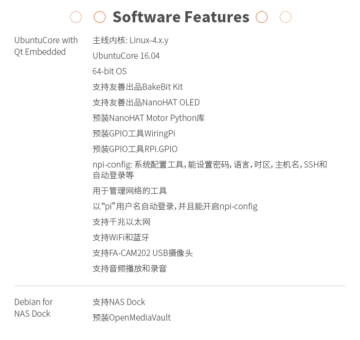
- mainline kernel: Linux-4.x.y
- 64-bit OS
- npi-config: system configuration utility for setting passwords, language, timezone, hostname, SSH and auto-login.
- auto-login with user account “pi” with access to npi-config
- supports Gbps Ethernet
- supports WiFi and Bluetooth
- supports FriendlyElec’s FA-CAM202 USB camera
- supports audio recording and playing
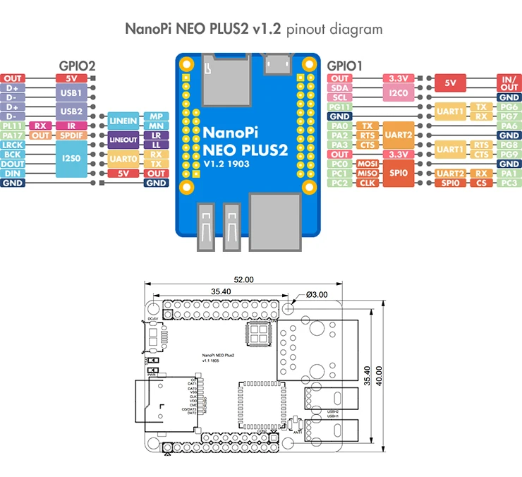
GPIO Pin Spec
| Pin# | Name | Linux gpio | Pin# | Name | Linux gpio |
| 1 | SYS_3.3V | 2 | VDD_5V | ||
| 3 | I2C0_SDA / GPIOA12 | 12 | 4 | VDD_5V | |
| 5 | I2C0_SCL / GPIOA11 | 11 | 6 | GND | |
| 7 | GPIOG11 | 203 | 8 | UART1_TX / GPIOG6 | 198 |
| 9 | GND | 10 | UART1_RX / GPIOG7 | 199 | |
| 11 | UART2_TX / GPIOA0 | 0 | 12 | GPIOA6 | 6 |
| 13 | UART2_RTS / GPIOA2 | 2 | 14 | GND | |
| 15 | UART2_CTS / GPIOA3 | 3 | 16 | UART1_RTS / GPIOG8 | 200 |
| 17 | SYS_3.3V | 18 | UART1_CTS / GPIOG9 | 201 | |
| 19 | SPI0_MOSI / GPIOC0 | 64 | 20 | GND | |
| 21 | SPI0_MISO / GPIOC1 | 65 | 22 | UART2_RX / GPIOA1 | 1 |
| 23 | SPI0_CLK / GPIOC2 | 66 | 24 | SPI0_CS / GPIOC3 | 67 |
USB/Audio/IR Pin Description
| NanoPi NEO Plus2 | ||
| Pin# | Name | Description |
| 1 | VDD_5V | 5V Power Out |
| 2 | USB-DP1 | USB1 DP Signal |
| 3 | USB-DM1 | USB1 DM Signal |
| 4 | USB-DP2 | USB2 DP Signal |
| 5 | USB-DM2 | USB2 DM Signal |
| 6 | GPIOL11 / IR-RX | GPIOL11 or IR Receive |
| 7 | SPDIF-OUT / GPIOA17 | GPIOA17 or SPDIF-OUT |
| 8 | PCM0_SYNC / I2S0_LRC | I2S / PCM Sample Rate Clock/Sync |
| 9 | PCM0_CLK / I2S0_BCK | I2S / PCM Sample Rate Clock |
| 10 | PCM0_DOUT / I2S0_SDOUT | I2S / PCM Serial Data Output |
| 11 | PCM0_DIN / I2S0_SDIN | I2S / PCM Serial Data Input |
| 12 | GND | 0V |
Audio
| Pin# | Name | Description |
| 1 | MICIN1P | Microphone Positive Input |
| 2 | MICIN1N | Microphone Negative Input |
| 3 | LINEOUTR | LINE-OUT Right Channel Output |
| 4 | GND | 0V |
| 5 | LINEOUTL | LINE-OUT Left Channel Output |
Debug Port(UART0)
| Pin# | Name |
| 1 | GND |
| 2 | VDD_5V |
| 3 | UART_TXD0 / GPIOA4 |
| 4 | UART_RXD0 / GPIOA5 / PWM0 |

Reviews
There are no reviews yet.